
As a beginning DIY electric guitar kit builder, you may find wiring the electronic components to be intimidating. If you are careful in your kit selection, you can find a good one with a pre-assembled wiring harness with plugs that eliminate all soldering. But what if the kit you chose isn’t plug-and-play? Are you looking at a pile of components and wires wondering what to do with them?
There are truly a lot of options when it comes to wiring your electric guitar. But for now, we will just keep it simple and basic. The really great thing is that you are not eternally bound to the decision you make now with your electronics. Changing pickup, pots, capacitors, or switches is relatively easy. You can even re-wire your existing components in a different way. Your instrument gives you the canvas where you can experiment with all kinds of different combinations.
So for starters, we will limit ourselves to the things that generally come in an off-the-shelf DIY electric guitar kit. We’ll stick to passive pickups with two leads, standard switches, and common volume and tone control circuits. In the future, perhaps we could look at 4-lead pickups, specialty switches, active preamps, coil splitting and a host of other options.
Common DIY Electric Guitar Kit Electronics
Your kit probably came with a pickup or set of pickups common to the guitar style of the kit, along with the standard switches and controls as needed.
If you bought a Strat-style kit, chances are all of the pickups and electronic components are already installed on the pickguard, commonly called a “loaded pickguard.” You will usually see three single-coil pickups, a 5-way switch, one volume control and two tone controls. They are already assembled and wired, and all you need to do is connect a ground wire to the tremolo bridge and install the output jack for the cable.
Your Tele style kit likely has the neck pickup already installed on the pickguard, but you will need to connect it. The control plate probably is pre-wired, so you will just attach the neck pickup and the bridge pickup to the switch. Those are usually single-coil pickups, but sometimes there are variations. Make sure you run the ground wire up under the bridge before tightening it down. Then attach the output jack and you are all set.
For your P- or J-bass kit, you generally also have a pre-wired pickguard or control plate. Again, make sure you run a ground wire up under the bridge. With all of these styles mentioned so far, most will have the volume and tone control circuits already assembled. Your task is just to connect the remaining wires.
Dual-humbucker guitars, such as LP and similar style kits, might be a little more complex. They usually have the controls mounted from the back of the guitar instead of on a pickguard or control plate. Many kits still have a pre-wired harness, but care will need to be taken to make sure the right component goes in the right place, even if it is already wired. Expect to spend a little more time with these electronic circuits.
The Volume Control Circuit
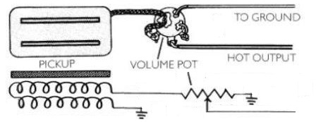
The volume control on your electric guitar is a variable resister, known as a potentiometer. The fact is, you could send the output of your pickups directly to the output of your guitar. In fact, if you are running your volume wide open – “10” – that is exactly what you are doing. The volume control on your guitar just divides the signal from the pickup between the output jack and ground. As the volume control is turned down, the resistance between the pickup and output increases. At the same time, the resistance between the pickup and ground decreases. When the volume is turned all the way down, the hot side of the pickup is shorted to ground.

A single humbucker pickup and single volume control is used in this Les Paul Jr. style guitar kit.
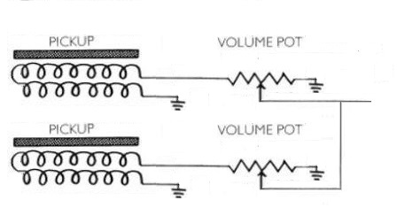
The volume control circuits can be wired in parallel for two pickups. This is a simplified version, without the switch and tone controls. Careful examination of this wiring reveals that if one of the pickups is turned down, both of them are shorted to ground leaving no output. This can be desirable to quickly kill all sound, but some might consider that a fault. If that effect is not desired, the two volume controls can be made independent of each other by connecting the pickup to the wiper connection on the pot.
The Tone Control Circuit
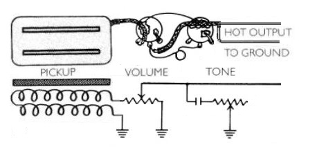
The tone control is also a variable resistor or potentiometer (pot), but another component is added. A capacitor is used to to pass only the higher frequencies, or trebles, through to the pot. Lower frequencies will not pass through the capacitor. So by placing a capacitor between the pickup output and ground, the higher frequencies are shorted to ground while the lower frequencies are sent to the output (or to the volume pot, depending on where it is placed).
The tone control pot is wired in series with the capacitor and determines how much of the treble frequencies are sent to ground. This type of circuit is known as a “treble bleed.”
The lower the value of the capacitor, the higher the frequency range that passes through. A very low value capacitor will pass only very high frequencies and some upper mid-range frequencies. The value determines the treble cut. Lower value capacitors will have give more treble, and higher values will have a darker, muddier tone.
A standard value used in electric guitar circuits with single-coil pickups (Strats or Teles) is are .047uf (microfarad). Humbucker pickups are often paired with .022uf capacitors. The standard capacitor used in a Jazz or Precision bass is .05uf.
Switches
Most electric guitars will employ a switch to select between the neck pickup, the bridge pickup, or both pickups or other combinations as applicable. Dual humbucker configurations like Les Paul generally employ a toggle switch. Fender style guitars like the Stratocaster or Telecaster use lever switches – typically five positions on a Strat or three positions on a Tele.
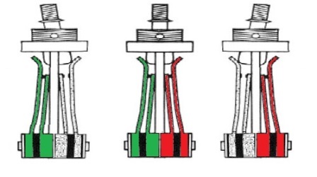
The two kinds of switches function differently. The toggle switch has both sides engaged in the center position, and moving from side to side breaks the connection on the opposite side. The lever switch connects a common lug to different positions as it is moved. Typically this lever switch has separately functioning parts on each side that move in tandem. Of course there are variations with each switch, and sometimes other switches such as mini toggles, slide switches, or push-pull switches are used.
Typical Wiring Diagrams
There are many different ways to wire your guitar. If you are a beginner with standard kit, here are some of the ones you will most likely encounter.
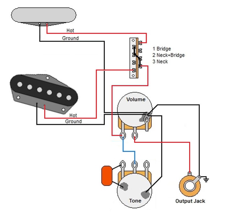
This is a typical wiring diagram for a Telecaster style configuration. It has two single-coil pickups and a three-way lever switch with one volume and one tone control. For this standard configuration, the pots are 250K and the capacitor is .047uf. If you are building a Tele-style kit, this is most likely what you will find on your pre-assembled or “loaded” control plate.
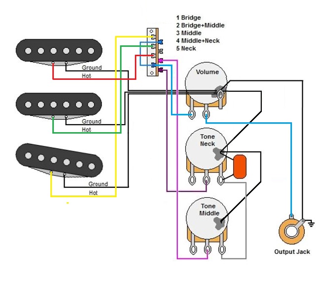
This is a typical wiring diagram for a Stratocaster style configuration. It has three single-coil pickups and a five-way lever switch with one volume and two tone controls. For this standard configuration, the pots are 250K and the capacitor is .047uf. If you are building a Strat-style kit, this is most likely what you will find on your pre-assembled or “loaded” pickguard.
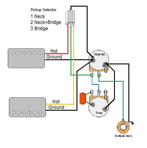
This is a typical wiring diagram for dual humbucker configurations such as the Les Paul Junior or Epiphone Les Paul Special. Many other guitars use this configuration. It has two humbucker pickups selected with a toggle switch, one volume and one tone control. For this standard configuration, the pots are 500K and the capacitor is .022uf. Similar to the previously described single-coil layouts, the pickup selector switch is placed in the circuit before the volume and tone controls.
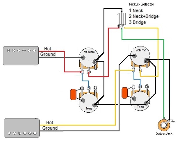
This is a typical wiring diagram for dual humbucker configurations in the ES hollow-body and standard Les Paul and SG guitars. Many other guitars use this configuration. It has two humbucker pickups selected with a toggle switch, two volume and two tone controls – one set for each pickup. For this standard configuration, the pots are 500K and the capacitor is .022uf. Because the volume and tone controls are specific to each pickup, the pickup selector switch is placed at the end of the circuit.
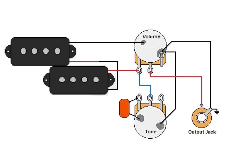
This is a typical wiring diagram for a Precision style bass. It has two single-coil pickups wired in series, so they act as a humbucker. There is one volume and one tone control. For this standard configuration, the pot is 250K and the capacitor is usually .05uf. If you are building a P-style bass kit, this is most likely what you will find on your pre-assembled or “loaded” control plate.

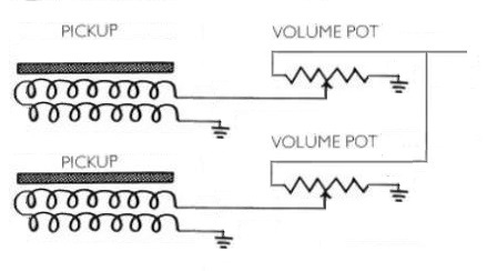
This is a typical wiring diagram for a Jazz style bass. It has two single-coil pickups with two volume control and one tone control without the use of a switch. Notice that the pickups are connected to the center lug, the wiper, of the pots. This prevents total loss of output when you turn just one pickup all the way down. For this standard configuration, the pots are 250K and the capacitor is usually .05uf. If you are building a P-style bass kit, this is most likely what you will find on your pre-assembled or “loaded” control plate.
Some bass guitar kits may come with one or two humbucker pickups, or with a combination of Jazz and Precision style pickups. The wiring is similar to the standard diagrams above.
There are many, many variations to these standard wiring diagrams. Listed here are the ones you are most likely to see in the kit you are building. If you feel up to the challenge, you can experiment with other wiring schemes, such as variations in the capacitor values or placement of the capacitor in the tone circuit.
If your humbucker pickup has four leads, you can find more distinct sounds by the way you switch between the two coils inside. You may also want to try adding a pre-amp for an active circuit and greater variation in tone (be sure to allow room for a battery). Some kits may come with three humbuckers, or a combination of humbucker and single-coil pickups – or you may try swapping these out yourself.
Additional Resources
Here are some additional resources for wiring your electric guitar. Clicking on these images of these books will open a link at Amazon. Be sure to read the reviews left by Amazon customers for more information.